


Évaluations - 7, GPA: 4.4
(

 )
)
|
Photos et spécifications Pioneer DEH-2200UB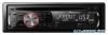 |


Par ce dispositif a également d'autres instructions :
Facilité d'utilisation
In this case, be sure to connect to both connectors. 13 Speaker leads White: Front left © White/black: Front left © Gray: Front right © Gray/black: Front right © Green: Rear left © Green/black: Rear left © Violet: Rear right © Violet/black: Rear right © 15 Yellow/black If you use an equipment with Mute function, wire this lead to the Audio Mute lead on that equipment. If not, keep the Audio Mute lead free of any connections. / _ 16 Blue/white Connect to system control terminal of the power amp (max. 300 mA 12 V DC). 17 Blue/white (6*) Connect to auto-antenna relay control terminal (max. 300 mA 12 V DC). 18 Blue/white (5*) The pin position of the ISO connector will differ depending on the type of vehicle. Connect 5* and 6* when Pin 5 is an antenna control type. In anothertype of vehicle, never connect 5* and 6*. 20 Connect with RCA cables (sold separately) 22 System remote control 25 Rear speaker 23 Left 1 1 24 Right I [\®J + e 25 Rear speaker , \ 26 Perform these connections when using the optional amplifier. Fig. 1 Abb. 1 Afb. 1 Pmc. 1 En En (Connections j ( ) Important • When installing this unit In a vehicle without an ACC (accessory) position on the Ignition switch, failure to connect the red cable to the terminal that detects operation of the Ignition key may result In battery drain. ACC position No ACC position • Use of this unit In conditions other than the following could result In fire or malfunction. — Vehicles with a 12-volt battery and negative grounding. — Speakers with 50 W (output value) and 4 ohm to 8 ohm (Impedance value). • To prevent a short-circuit, overheating or malfunction, be sure to follow the directions below. — Disconnect the negative terminal of the battery before Installation. — Secure the wiring with cable clamps or adhesive tape. Wrap adhesive tape around wiring that comes Into contact with metal parts to protect the wiring. — Place all cables away from moving parts, such as the gearshift and seat rails. — Place all cables away from hot places, such as near the heater outlet. — Do not connect the yellow cable to the battery by passing It through the hole to the engine compartment. — Cover any disconnected cable connectors with Insulating tape. — Do not shorten any cables. — Never cut the Insulation of the power cable of this unit In orderto share the power with other devices. The current capacity of the cable Is limited. — Use a fuse of the rating prescribed. — Never wire the negative speaker cable directly to ground. — Never band together negative cables of multiple speakers. • When this unit Is on, control signals are sent through the blue/white cable. Connect this cable to the system remote control of an external power amp orthe vehicle's auto-antenna relay control terminal (max. 300 mA 12 V DC). If the vehicle Is eguipped with a glass antenna, connect It to the antenna booster power supply terminal. • Never connect the blue/white cable to the power terminal of an ex...
Ce manuel est également adapté pour les modèles :Unité - DEH-2200UBB (836.06 kb)
Unité - DEH-2220UB (836.06 kb)