


Évaluations - 3, GPA: 4
(

 )
)
|
Photos et spécifications Yamaha YHT-298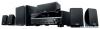 |


Par ce dispositif a également d'autres instructions :


Facilité d'utilisation
The follo w ing cab les (no t sup p lied ) ar e r e quir ed to b u ild the system de scrib e d in this docu ment. • S peaker cables (x5) • H DMI cable (x2) • A ud io p i n cable (x1) • D ig ital optical le (x1) (n ot r e quir ed if you r T V suppor t s AR C [A udio Ret u r n Chan nel] ) 1 P r epar a t ion Acce s s o r i e s .. Remote contro l .. Batter i es (AAA, R0 3, UM-4) (x2) Insert the batteries th e right way round. .. A M antenna .. FM antenna .. Y PAO microphone .. CD-R O M (Owner’s Manual) .. Safety Brochure .. E a sy Setup Guid e • T he illustr a t i ons of the remo te control used i n this guide are of the U . S . A. model. • ( A u str a lia mode l only) F o r inf o r m ation on ho w to contro l e x t e r n al de v i ces with the remo te control, ref e r to “Su pplement f o r Remote C ontrol” on the su pplied CD-R O M. C a bles r e quir ed f o r c o nnec tions * T h e s u pplie d FM a n t e nn a vari es depending on the regi on of pur c h a s e . Easy S e tup Guide English A V Rec e iv er Th is do cu men t e x pla i ns h o w to set u p a 5. 1- chan ne l syst em a nd pla y b a c k sur r oun d so un d fr om a BD/ D VD o n th e un it. T o r e duce the impac t on natural r e so ur ces , the O w ner's M a nual f o r this pr odu c t is sup p lied on CD -ROM. F o r m o r e inf o r m a t i o n abou t this pr o d uc t , r e f e r t o the O w ne r's M a nual o n the sup p lied C D -ROM. PDF v e rsi o ns o f thi s guid e and “ O wn er ’ s M a nual ” can be downl o a d ed f r o m the f o l l owing w e bsite . yamah a.c o m/ 3065_ fm December 21 01 PM 2 En S e t up the speakers in the r oom using the fo llowing d i ag ram as a r e fer e n ce. F o r infor m ation on other sp eaker systems, r e fer t o “ O wne r ’ s Man ual”. 2 Placing speak e rs 123 45 9 1 F r ont sp eaker (L) 2 F r ont sp eaker (R ) 3 C enter spe a ker 4 S u rr ou nd speaker (L) 5 S u rr ou nd speaker (R) 9 S u bw oofer 10 ° to 30 ° 1 0 ° to 30 ° 3065_ fm December 21 01 PM En 3 ¦ C o nnec t ing speak e r cables S p eaker cables have two wir e s. One is for co nnecting th e negative (-) ter m inals of the u n it an d the spea ker , a n d the othe r is for the positive (+) ter m inals. If the wir e s a r e color ed to p r eve n t confusion, con nect the black wir e to the neg ative and the other wir e to the p o sitive te r m inals. (Con nec t ing fr o n t speake r s ) a Re mo v e ap pr o x imat el y 1 0 mm (3 /8 ”) o f in s u la ti on fr om t he e nds of t h e sp eak e r c a b l e an d tw is t t h e b a r e wi r es o f t he c a b l e fi r m l y to ge t her . b Lo os en t h e s p e a k e r te r m in al . c I nse r t t h e b a r e wi r es o f t h e ca b l e in to th e g ap o n t h e si de ( u p p e r r i g h t o r b o tto m le ft) o f t h e te r m in al . d Tig h t e n th e te r m in al . Us i n g a b a na n a pl u g (U.S.A., Canada , Australia and Ge neral models only) a Ti gh te n t he s pea k e r te r m i n al . b In se r t a ba na na p l u g i n t o t he e nd o f t h e t e r m i n a l . (Con necting center/surr o u n d sp eaker s) a R e mo v e ap pr o x imat el y 1 0 mm ( 3 /8 ”) o f i n s u l a ti on fr om th e en ds o f t h e spe ak e r ca b l e an d tw is t t h e b a r e wi re s of th e ca b l e fi r m l y to ge th er . b Pr ess do wn t he t a b . c In se r t th e ba re wi re s of th e ca b l e i n to t h e ho le i n t h e te r m in al . d R e le as e the t a b . 1 Connect the fr ont spe ake r s ( 1 / 2 ) to the FR ONT ( / / \ ) terminals. 3 C o nnec t ing speak e rs/sub w of er • ( U . S . A. and Cana da models only) Under its d e f a ult settings , the unit is con f igured f o r 8-ohm speak ers . When conne cting 6-ohm spea k e rs , set the unit’ s speak er impe dance to “6 . MIN ” . F o r details , se e “Setting the speak er impe dance” in “Owner’ s Man ual”. • U se a sub w oof er equipped with b u ilt-in amplifier . • B ef ore conn ecting the spea k e rs , remo v e the u n it’ s po w e r cab l e from the A C w a ll outlet an d tur n off the subw o o f e r . • E nsure th at the core wires of the speak er ca b l e do not touch each other or come into contact with the u n it’ s metal areas . Th is ma y damage t he unit or the s peak ers . If t he speak er cab l es shor t circuit, “Chec k SP Wires” wil appear on th e front displa y when the unit is tur ned on. FR ONT a b c d - ( b lack) + (red ) F RO N T a b B anan a p l ug RO U ND CENTER a b c d + (r ed) - ( b lack) FR ONT SURR OUND SUBW OOFER CENTER SPEAKERS 123 45 9 T h e unit ( r ear ) 3065_ fm December 21 01 PM 4 En 2 Connect the ce nter s p ea ker ( 3 ) to the CENTER te rminal. 3 Connect the surr ound spea ker s ( 4 / 5 ) to the S URR OUND ( // \ ) terminals. 4 Connect the subw oof e r ( 9 ) to the S UBW OOFER ja c k . FR ONT SURR OUND SUBW OOFER CENTER SPEAKERS 123 45 9 The unit (rea r ) FR ONT SURR OUND SUBW OOFER CENTER SPEAKERS 123 45 9 The un it (re ar) FR ONT SURR OUND SUBW OOFER CENTER SPEAKERS 123 45 9 T h e u n it ( r ear) Au d i o pi n c a bl e 3065_ fm De...