


Évaluations - 1, GPA: 3
(

 )
)
|
Photos et spécifications Canon VB-M600VE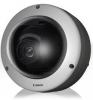 |


Par ce dispositif a également d'autres instructions :
Vidéo - VB-M600VE (10.84 mb)
Vidéo - VB-M600VE (619.05 kb)
Facilité d'utilisation
approx. 8.4 W Max. approx. 7.8 W Max. approx. 8.6 W When using AC Adapter PA-V17: Max. approx. 10.72 W Max. approx. 10.2 W Max. approx. 10.9 W When using DC: Max. approx. 9.0 W Max. approx. 8.3 W Max. approx. 9.0 W When using AC: Max. approx. 8.1 W Max. approx. 7.5 W Max. approx. 8.3 W Max. approx. 18.7 W* Max. approx. 18.9 W* *when separately sold Heater Unit HU600-VB installed Dimensions ( x H) 180 x 147 mm ( 7.09 x 5.79 in.) ( x H) 186 x 140 mm ( 7.32 x 5.51 in.) Weight Approx. 1920 g (4.24 lb.) (camera only) Approx. 162 g (5.8 oz.) (Junction Box Mounting Kit) Approx. 1910 g (4.22 lb.) (camera only) Approx. 162 g (5.8 oz.) (Junction Box Mounting Kit) Approx. 1200 g (2.65 lb.) (camera only) Approx. 159 g (5.7 oz.) (Junction Box Mounting Kit) Approx. 1200 g (2.65 lb.) (camera only) Approx. 159 g (5.7 oz.) (Junction Box Mounting Kit) Impact Resistance External materials: aluminum alloy, Dome: polycarbonate plastics With lens shock absorbing mechanism Estimated shock resistant: 50J (based on Canon’s test method) Dust-resistant/ IP66-rated (IEC60529) Waterproof Specification Only applies if properly installed and adequately waterproofed *1 (W): maximum wide angle, (T): maximum telephoto *2 The frame rate may be reduced due to Viewer PC’s specs, the number of clients accessing at the same time, network loads, image quality setting, type or movement of the subject or other reasons. *3 A third-party amplifier speaker is necessary. *4 VB-H610VE/VB-H610D specific function 3/4” NPT threaded hole 3- 4.6 ( 0.18) (mounting screw holes) 3- 4.6 ( 0.18) (mounting screw holes) 140 (5.51) R62 (R2.44) 12° 120° 120° 155 ( 6.10) R62 (R2.44) 147 (5.79) 7.5° 120° 120° 164 ( 6.46) Unit: mm (in.) WARNING To reduce a risk of fire or electric shock, do not expose this product to rain or moisture. CANON INC. 30-2, Shimomaruko 3-chome, Ohta-ku, Tokyo 146-8501, Japan CANON EUROPA N.V. Bovenkerkerweg 59-61, P.O. Box 2262, 1185 XB Amstelveen, The Netherlands The contents of this guide are subject to change without any prior notice. Cable Wiring Method For VB-H610VE/VB-M600VE, secure the various cables with the cable clamps fastened to the camera to prevent damage to cables or connectors due to vibration, etc. *The diagram is a wiring example for VB-H610VE/VB-M600VE. LAN cable Audio interface cable (included) Heater unit HU600-VB (sold separately for VB-H610VE/VB-M600VE) Installing the Camera The following describes procedures for mounting the camera to a ceiling. Before installing the camera, set the IP address and other network information on the camera using the “VB Initial Setting Tool” on the Setup CD-ROM. For details on how to operate the “VB Initial Setting Tool”, see “Operation Guide”. 1 Determine an installation position for the camera and drill holes in the ceiling Use the included template to determine the positions of the fixing screw holes and wiring hole ( 40 mm ( 1.6 in.)) according to the camera orientation. Next, cut out the wiring hole, and drill the fixing screw holes in the the ceiling. 2 Loosen the three lock screws on the dome case and remove the dome case Special temper-resistant screws are used for the dome case lock screws. Use the included dome case lock screw wrench. 3 Remove the tape and the inner cover Remove the 4 pieces of tape that prevent lens rotation during shipping, and push the inner cover in the direction of the arrows to remove it. Then remove the 2 pieces of tape attached to the base of the lens. 4 Open the wiring hole according to the installation method Use a box cutter to cut a cross shape into the wiring hole cover in order to guide cables through. Do not remove the wiring hole cover. Use a coin to unscrew the wiring hole cover from the side through which cables will be guided. Screw the wiring hole cover into the other wiring hole. You can fit a composite pipe (NPT 3/4 inch threaded hole) to the wiring hole. 5 Secure the safety wire Securely attach the safety wire to an anchor or structure. After securing one end of the safety wire to the ceiling, secure the other end to the camera using the screw that is fastened to the camera. 6 Guide the LAN cable through the wiring hole When using an external power supply, guide the power interface cable through the wiring hole. Guide the I/O interface cable and the audio interface cable (included) through the wiring hole if necessary. Important When using the AC Adapter PA-V17 (sold separately), cut the cable tie and remove the ferrite core. Be sure not to damage the power cable when cutting the cable tie. Cable tie 7 Fix the camera to the ceiling Fix the camera at three points to the ceiling using the appropriate screws. Three 4.5 mm ( 0.18 in.) ceiling fixing screw holes are located on the camera. You must provide screws that correspond to the ceiling fixing screw holes. 8 Wire the cables Wire the cables referring to “Cable Wiring Method”. Important When wiring is complete, seal the wiring hole to keep out insects and dust. 9 Attach the inner cover Atta...
Ce manuel est également adapté pour les modèles :Vidéo - VB-H610D (7.88 mb)
Vidéo - VB-H610VE (7.88 mb)
Vidéo - VB-M600D (7.88 mb)